This is a new generation of LV Pole Mounted Breaker developed by HAIVO Electric in accordance with the French market.
This product uses air as the insulating medium, and adopts a knife contact and grid arc extinguishing structure.
Moreover, this product utilizes an integrated digital trip unit in conjunction with a load indicator to achieve the operating time compliant with the HN63-S11 standard and the cumulative overload tripping function.
Users can adjust the integrated digital trip unit as needed, with three power ratings available: 50kVA, 100kVA, and 160kVA.
The external pointer of the load indicator serves dual purposes: displaying load status and allowing users to rotate it to set the required cumulative trip time. This pointer adjustment feature employs stepless adjustment,.offering greater operational convenience.
Users can apply padlocks at the ground-level operating handle to prevent unauthorized personnel from operating the equipment, thereby ensuring power supply security.
LV Pole Mounted breaker/digital trip unit
The protection and management of MV/LV transformers in a rural environment requires specific circuit breakers compatible with significant load differences,thus ensuring full exploitation of the installed power, even in unbalanced operation.
1-Post circuit breaker with digital trip unit
| circuit breakers |
| D165T | D265T |
| Reference strandard | NH63-S-11 | NH63-S-11 |
Voltage rating
Current rating | 440V
165A | 440V
265A |
Cutout power
Closing power | 4000A
6800A | 6400A
11700A |
Number of poles
Number of outputs | 4
1 output | 4
2 outputs |
| Cable sections | 25/70mm*2 | 50/150mm*2 |
Breakdown voltage
• pulse/earth
• at 50Hz
• between poles |
20kV
10kV
4kV |
20kV
10kV
4kV |
| Control system | Manual | Manual |
| Installation | on post | on post |
Description Circuit breaker unit These units (4 poles 3 of which are protected) cut off in air with metal partition chambers to break the arc.
When the circuit breaker is open, a contact makes an electrical link between the transformer neutral and the station structural earth.When the circuit breaker is closed, a spark gap limits the rise in potential of the LV neutral, in relati.n to the structural earthing, for a value exceeding 10 kV.
The circuit breaker is installed inside a weatherproof GRP case.
2 - Digital trip unit
| P=50kVA | P=100kVA | Trip time | P=160kVA | Trip time |
| U =440v | U =440v | U =440v |
| I=72.2A | I=144.3A | I=231A |
| Currant in each phase (in A) | Currant in each phase (in A) | Currant in each phase (in A) |
| 1 | 2 | 3 | 1 | 2 | 3 | Min | Max | 1 | 2 | 3 | Min | Max |
| Temperature=+20ºC |
| Initial load | 48 | 48 | 48 | 96 | 96 | 96 |
|
| 155 | 155 | 155 |
|
|
| Triphase balanced overload | 85
100
160
950
2000
58
58
58
0 | 85
100
160
950
2000
58
58
58
0 | 85
100
160
950
2000
120
160
220
950 | 170
200
320
1900
4000
116
116
116
0 | 170
200
320
1900
4000
116
116
116
0 | 170
200
320
1900
4000
240
320
440
1900 |
1h35
25mn
30s
0.02s
0.02s
1h50
15mn
30s
0.02s
|
1h10
6mn
0.2s
0.05s
50mn
7mn
0.2s | 280
320
500
3000
5640
6400
185
185
185
0 | 280
320
500
3000
5640
6400
185
185
185
0 | 280
320
500
3000
5640
6400
400
500
700
3000 | 55mn
26mn
30s
0.02s
0.015s
0.015s
32mn
11mn
30s
0.02s | 1h10
7mn
30s
0.1s
0.025s
0.02s
33mn
4mn
0.1s |
| Temperature=-25ºC |
| Initial load | 76 | 76 | 76 | 152 | 152 | 152 |
|
| 240 | 240 | 240 |
|
|
| Triphase balanced overload | 110
130
190
87
87
87 | 110
130
190
87
87
87 | 110
130
190
130
130
130 | 220
260
380
174
174
174 | 220
260
380
174
174
174 | 220
260
380
260
360
480 | 1h
14mn
30s
2h15
10mn
30s |
44mn
5mn
30mn
6mn | 350
420
600
280
280
280 | 350
420
600
280
280
280 | 350
420
600
420
560
760 | 1h
14mn
30s
2h15
13mn
40s |
45mn
5mn
48mn
5mn40s |
| Temperature=+50ºC |
| Initial load | 25 | 25 | 25 | 50 | 50 | 50 |
|
| 80 | 80 | 80 |
|
|
| Triphase balanced overload | 70
90
160
48
48
48 | 70
90
160
48
48
48 | 70
90
160
100
130
200 | 140
180
320
96
96
96 | 140
180
320
96
96
96 | 140
180
320
200
260
400 | 1h30
20mn
45s
1h
15mn
30s |
1h07
5mn
1h
7mn | 231
300
500
155
155
155 | 231
300
500
155
155
155 | 231
300
500
320
420
650 | 1h5
17mn
35s
1h
15mn
30s |
1h05
5mn
40s
1h
7mn
|
Trip time as per HN 63-S-11 + corrected values (in bold type) to match the selectivity of the TPC fuses.
Digital Trip Unit The Digital Trip Unit protects the three ratings of the post-mounted transformer (50 kVA, 100 kVA and 160 kVA) , whether it be a conventional transformer (no internal protection) or a new transformer with protection (TPC).
The transformer protection rating is set by a selector.
The micro-controller assesses the transformer temperature in real time, based on the currents in the three phases and the external ambient temperature. This ambient temperature is computed based on the probe and a mathematical model that is also a function of the three phase currents.
Working Ambient

Temperature: -40°C ~ +70°C
Humidity: 100%
Altitude: ≤2000m
Wind speed :≤40m/s • H
Note: No fire, no explosion hazards, no chemical c.rrosion and recurrent severe vibration.

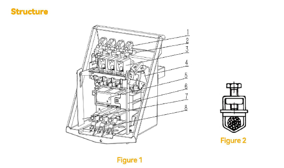
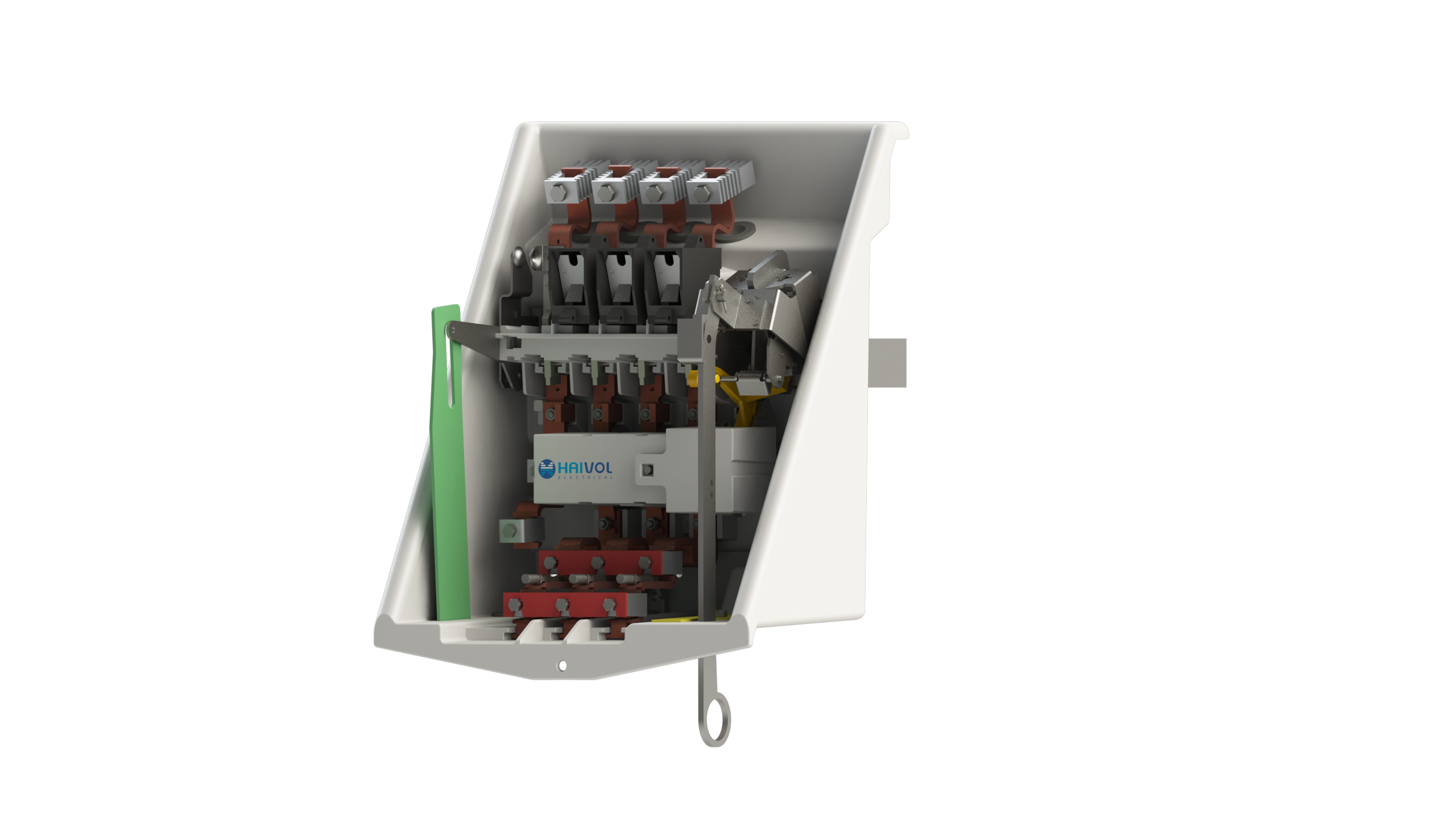
1.lncoming wiring clamp
2.lncoming wiring hole
3.Arc chute grid
4.Operation mechanism
5.Digital trip unit
6.Load indicator trip indication
7.Position indicator
8.Operation handle
1.Incoming wiring clamp Users can connect the transformer1s low-voltage side or other four-phase (3P+N) power sources as the incoming power supply for this circuit breaker. Additionally, its unique design eliminates the need for users to crimp lugs before connection (as shown on figure 2).
Additionally, the wiring clamps below it serve as outgoing and phase sequence must be ensured during connection.
2. Incoming wiring hole Users can insert cables into the circuit breaker at this location. Similar to point 1, its lower section is designed for outgoing connections.
3. Arc chute grid This grid is designed to extinguish arcs during circuit breaker operation. Users can replace this component based on the current condition of the grid.
4. Operation mechanism This area houses the circuit breaker's operating mechanism. Designed as a spring-charged closing mechanism with a trip-free release, it can be operated via a floor-mounted handle.
5. Digital trip unit Digital Trip Unit, distinct from traditional thermal trip units or fixed-function PCB hardware trip units, features embedded current transformers with phase-toneutral voltage supply. It complies with the trip response time and accumulated overload response time specified in the HN63-S11 standard. The capacity is configurable to 50, 100, or 160 kVA as required.
6. Load indicator trip indication The orange component will drop down when the accumulated load time is reached (indicated by Component 6 rotating clockwise past the O position) and Component 10 is in the configuration shown. This action will internally trigger the circuit breaker to trip.
7. Position indicator The green component protrudes minimally at the bottom when in the closed position.When in the open position, a significantly longer section becomes visible.
8. Operation handle This handle connects to the floor-mounted operating handle. During installation,users must secure the linkage pin with a split pin. Downward movement initiates tripping/spring-charging, while upward movement performs the closing operation.
9.Load trip enable/disable handle This handle enables or disables the trip function of the load indicator.
Downward position:
Operate the 9# Operation Handle downward to charge the mechanism, then upward to cl.se the circuit breaker. During this motion, the 7# Load lndicator Trip Indication resets. If the circuit breaker detects overload, the 6# Load Indicator activates When its pointer rotates clockwise past the O position, the breaker trips.
Inward position: The load indicator continues monitoring but disables tripping.

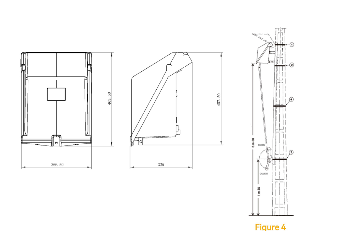
Figure 4 shows the installation diagram. The floormounted operating handle connects to the circuit
breaker via a standard iron pipe. The illustrated utility pole is circular; if a square utility pole is used,
this must be specified in the installation notes.


